| Home |
| Email John |
| Created 08/13/09 Last update 12/08/2010 |
Flux Concentrator

Most of the time when an induction heater is used, the work coil is simply wrapped around the work to be heated. Simple and direct. However, there are situations where simple wrapping won't work. A neon electrode is one example. Sweating or brazing a copper pipe is another. Still other situations involve needing to concentrate the heating in a small and specific area, smaller than a coil could be wound. In these cases a flux concentrator fills the bill.
Several companies make ferrites that can be machined or formed or otherwise conformed to the work. They all have one thing in common. They're expensive. In this article I'll show the work we've been doing with a concentrator made from transformer cores.
What is a Flux Concentrator?
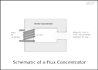
Simple. It is a magnetic material with a permeability greater than air (which equals 1) which constrains the field - more or less - to where you want it and doesn't itself get hot in the process. Here's a schematic of a concentrator like we're working with.
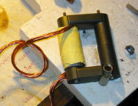
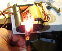
If it strikes you that this looks suspiciously like a transformer but with only one winding, you would be correct. We're using the same core material as we use to make the transformers. That's the cheap way out and it actually works quite well. Here is a photograph of the actual device.
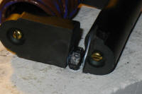
You'll notice several things about this setup. First is the use of Litz wire, in this case double stranded to handle the current. Second, there are no air gap spacers between the core parts. We want as good a magnetic path as we can get right up to the air gap where the object to be heated is located - in this case a copper butt splice.
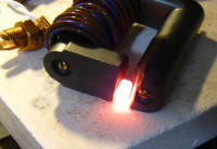
Here are a couple more photographs of a small object, in this case a nut, being heated.
Right after I took the last photo, the nut melted and the molten steel ate a nice hole in my refractory board!
Here's yet another example - heating a neon electrode without having to wrap anything around it.
Reactive Power
One can simply connect a flux concentrator up to the secondary of the Royer transformer and heat things. This is not an optimal setup, though, because the concentrator, being an inductor, draws a lot of lagging reactive power. That power has to be supplied by the transistors and that severely limits what one can do with the unit.
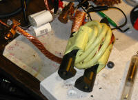
The solution is to use capacitors to supply leading reactive power or VARs to counteract the lagging VARs that the coil draws. If this seems like power factor correction, it is exactly what it is. If it seems like setting up a tank circuit, that's also exactly what it is. Here's a photo of a typical hookup.
The various parts are labeled. Basically, all that is involved is connecting some capacitors in parallel with the flux concentrator and the transformer secondary. The capacitors supply the reactive current and the inverter supplies the real current.
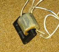
Now the current in the work coil - capacitor loop - also known as a a tank circuit - can be quite high without overloading the transistors. Amp-turns are what we're after so the more current and/or the more turns the better. Here's a work coil set up for very high current.
The wire used is 4 gauge equivalent Litz wire. You can see the resonating capacitors in the background. One other thing that you might notice is that there are two cores under the winding. This is because the single core was saturating at the high amp-turns this setup generates. It would seem like this would distribute the flux over a larger area but it didn't seem to affect performance. I later completed the magnetic circuit with a second set of pole pieces which performed just about like the single one.
Once the capacitors are added, two issues arise. One is what frequency to resonate the tank at and the other is how to deal with the heavy current. I like to resonate the work coil and capacitor tank at about 30 to 50% lower frequency than the free running unloaded Royer frequency. If the frequencies are close enough, one sees a smooth sine wave in the transformer primary current like this
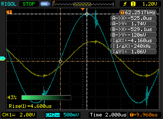
The yellow trace is the current in one leg of the transformer primary at 20 amps per division while the blue trace is the current flowing in the secondary loop.
If the frequency of the Royer is just a bit too high you'll see something like this
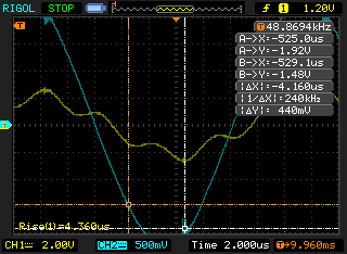
The setup is as before. As you can see, the Royer is trying to oscillate at a higher frequency then the tank's resonant frequency.
If the Royer frequency is very high, this is what you get
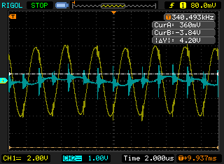
In this instance, the Royer has taken off on its own at about 340khz, the transistor/transformer current is very high and almost no power is being delivered to the load (blue trace). Caution: If full power is applied to the heater when this condition exists, the transistors will instantaneously burn out. This scope shot was taken with only about 30 volts being applied to the line in via a Variac. I must repeat: This condition is instantly destructive!
High Current and Heat Buildup.
As I noted above, it is the amp-turns that get the job done (Oersteds for us old-fashioned folks.) We can get the needed amp-turns either by using a few turns and lots of amp or many turns and fewer amps. Of course, it takes a higher voltage to push the amps through that higher turns count. I chose to go with the high voltage, low current route.
I had Garett wind me a lovely high voltage transformer.
It has 18 total turns on the primary and 50 turns on the secondary. I later added 10 more. This produces about 1.5kV of RF. The CDE metal film capacitors that we use for resonating capacitors are rated to 2000 volts so we're good to go there. You probably noticed in the photos above that the Litz wire was tape-wound. This is to provide extra insulation. Some of the setups had as much as 150 volts per turn across the concentrator coil!
I tested every work coil turns count combination from 20 to 11. For general purpose work, 14 to 15 turns and enough capacitors to resonate the whole thing at about 80khz is a nice sweet spot. On the Roy side, I used 2 0.047uF 2000 caps in place of the standard 0.15uF one. For the caps in parallel with the work coil, I used 2 to 3 (varies according to winding style) 0.047 2000 volt caps. This setup delivered about 700 net watts to the load. That is a lot, especially when focused in such a small gap.
That's about it for now. This is an area where we are actively researching. One of our goals is to make a small portable unit capable of brazing copper tubing. We're investigating other ferrites and even other drive methods. Stay tuned for future developments.
